

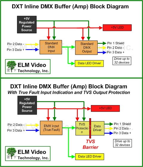
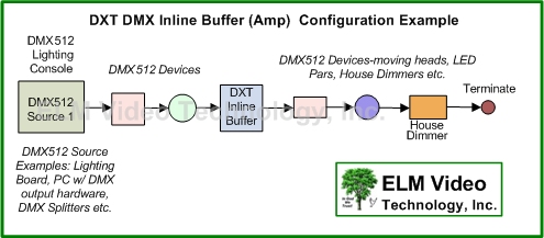
The DXT-PCB is a DMX 512 In Line Buffer PCB. With the tiny footprint PCB, install in any device that needs DMX buffering or driving. The DXT will source up to 32 DMX devices.
If you need voltage protection and true fault LED indications, the chipset can be upgraded which provides TVS (Transient Voltage Suppression) protection IC and a true fault input indication IC.
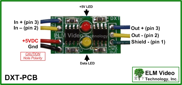
Features a power and data LED. Requires a +5V regulated power source.